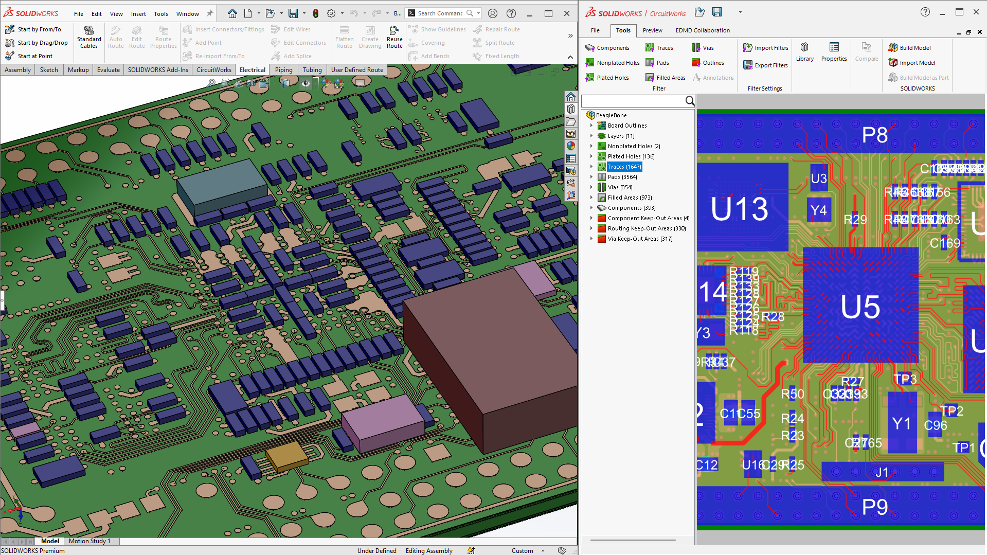
What is CircuitWorks?
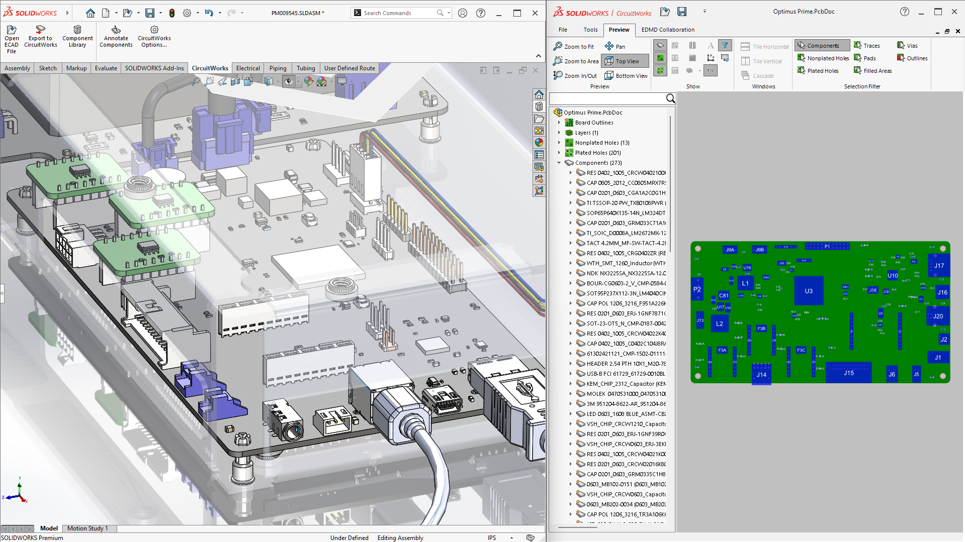
CircuitWorks is an add-in available in SOLIDWORKS Design software. CircuitWorks brings PCB design into the SOLIDWORKS ecosystem, enabling greater integration between ECAD and MCAD teams. A collaboration tool, CircuitWorks enables users to both import PCB layout information directly to their parametric SOLIDWORKS designs, and define assemblies within SOLIDWORKS that can then be sent to the PCB tool of your choice. This bidirectional design means CircuitWorks works the way you do without disrupting your current workflow.