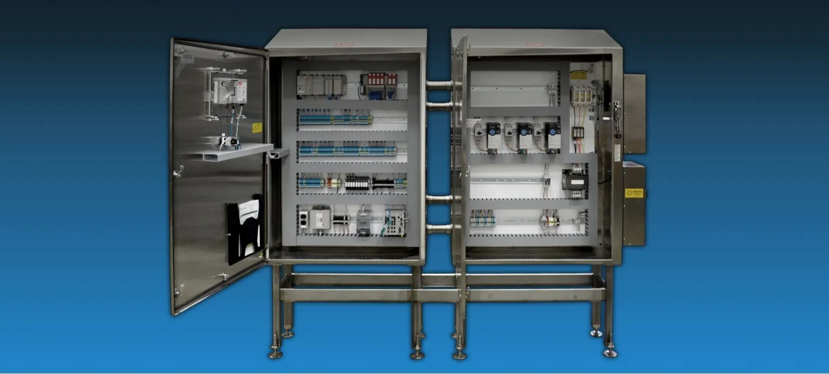
Select Technologies, Inc. (STI) is a full-service food plant equipment systems integrator specializing in design-build- installation and production-line automation services for process, material handling, and plant facility/utility systems. The company’s comprehensive process can yield cost-effective, highly detailed, and reliable systems even under the most challenging and difficult engineering requirements. STI’s services include mechanical systems design, production line layout, electrical design, automation, ammonia refrigeration, UL 508 panel building, IT integration, and HVAC mechanical services.
Because STI’s automation projects typically require the use of programmable logic controllers (PLCs) and electrical systems, STI tends to do a much higher volume of electrical schematics and panel design layouts than mechanical design, according to IT Manager Shane Trotter. “Until 2013, we used AutoCAD® LT 2D drawing software to create electrical schematics for our projects, yet we knew there had to be a better software solution out there because practically everything that we did in AutoCAD LT was tedious and done manually, including whenever changes were required,” Trotter explains.
“For example, if you have a 100-page drawing packet, and needed to slip a new drawing in at page 52, you would have to manually edit the page numbers in every title block from pages 53 to 100 manually,” Trotter notes. “We came to realize that working in a manner that required so much manual entry was slowing us down and impacting quality, so we began investigating a replacement solution that not only would eliminate our manual entry issues but would also integrate with our internally developed central parts database, which is Microsoft® SQL Server-based.”
STI’s search for a better electrical schematics solution led the company to evaluate the SOLIDWORKS® Electrical Schematic and EPLAN® software solutions. The company chose SOLIDWORKS Electrical Schematic Professional software because it utilizes the same Microsoft SQL Server database as STI’s parts database and provides access to an open Application Programming Interface (API), which enabled STI to integrate the solution with its central parts database. “The SOLIDWORKS API and the fact that SOLIDWORKS Electrical is Microsoft SQL Server-based were the deciding factors,” Trotter recalls. “EPLAN had a proprietary database, whereas the SOLIDWORKS solutions had a back end in a database that we could use the API to get to and integrate and automate the solution with our existing systems.”
FASTER DRAWING TIME THROUGH AUTOMATION OF MANUAL TASKS
Since implementing SOLIDWORKS Electrical Schematic Professional, STI has realized a range of productivity improvements associated with automating formerly manual tasks by integrating the software’s database with the company’s central parts database, which now contains roughly 500 electrical symbols, 500 2D layouts, and 2,500 manufacturer’s part numbers. Items that have been automated via SQL integrations include serial number labels, fuse lists, material lists, wire labels, terminal labels, backplate labels, material imported into STI’s custom Manufacturing Execution System (MES), and 2D panel layouts. Items still being automated include engraved or printed legend plates on switches and PLC input-output lists.
