ECADの概要

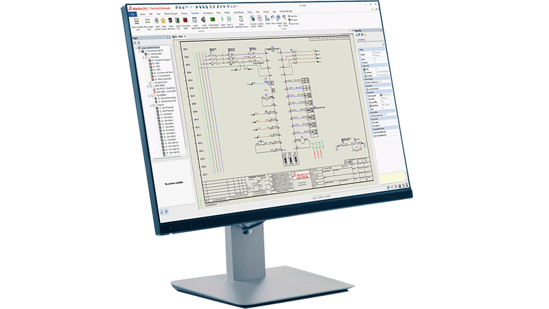
ECAD (Electronic Computer Aided Design/Electrical Computer Aided Designの略)は、製造に着手する前の段階で電気・電子システムの設計、文書作成、および検証を行うためのエンジニア向けソフトウェアです。産業用制御パネルのレイアウト、機械フレームへのワイヤ ハーネスの配線、組み込みシステム用のプリント基板の設計まで、ECADソフトウェアなら高い精度と構造、自動化によって作業を正しく遂行できます。

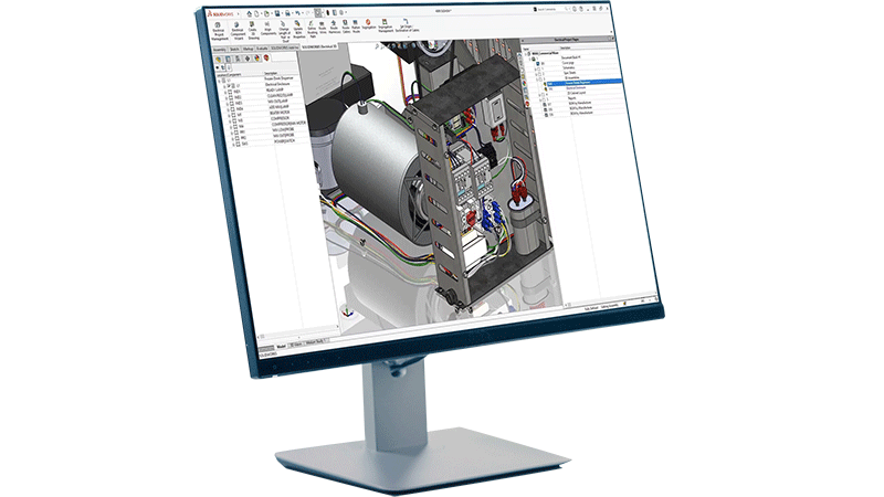
この用語が対象とする設計業務は、多岐にわたります。従来の電気エンジニアリング分野では、電気回路図、端子ストリップのレイアウト、ワイヤやケーブルの文書作成、およびパネル設計を指します。電子回路分野では、プリント基板(PCB)のレイアウト、回路設計とシミュレーション、および設計ルールのチェックにまでその領域が広がります。どちらの分野でもECADが必要とされており、現在ではお互いの連携がますます重要になっています。

電気システムと機械システムの統合がますます進む中、ECADは現代の製品開発を支える基盤として重要な役割を果たし続けています。ECADは単なる製図ツールにとどまりません。エンジニアリング チーム間の連携、多大なコストにつながるミスの削減、そしてコンセプトから生産までのリード タイム短縮を実現する設計環境なのです。

従来の電気エンジニアリングにおけるECAD

産業用システムや制御パネル、複雑な機械を手がける電気エンジニアにとって、ECADは設計プロセスの根幹をなすツールです。彼らは部分的なコンポーネントの設計にとどまらず、システム全体を俯瞰して設計を進めるからです。具体的には、適切な電力配分の決定から制御ロジックのレイアウト、各ワイヤおよび端子のドキュメント化、さらには最終製品の安全な製造、検査、および保守性の担保まで、すべてを担うことになります。

icon depicting schematic design creation

Electrical Schematics

Electrical schematics are the starting point. ECAD tools allow engineers to create detailed, standards-compliant schematic diagrams that define how electrical components connect and interact. Unlike generic drawing tools, purpose-built, intelligent ECAD software automatically links the schematic to downstream documentation, so a change in one place propagates across the entire project. This kind of electrical design automation is key to accelerating product development and reducing errors introduced by continual manual edits.

icon depicting wire harnessing in SOLIDWORKS on a desktop screen

Wire Harnessing

Wire harnessing adds another layer of complexity. In machines, vehicles, and industrial equipment, wire harnesses route power and signals through a physical structure. ECAD tools let engineers define the harness topology, specify wire gauges and colors, generate cut lists, and produce formboard drawings that manufacturing teams can use directly on the shop floor. Design for manufacturability, especially for wire harnessing applications, is crucial to align teams and reduce unnecessary roadblocks in the product development process.

interconnected squares showing a connected workflow, in this case representing terminal strip layout

Terminal Strip Layout

Terminal strip layout is another area where ECAD delivers real value. Manually arranging and documenting terminal blocks is time-consuming and error-prone. ECAD tools automate the generation of terminal strip diagrams directly from the schematic, ensuring that the physical layout matches the design intent without manual re-entry.

icon depicting virtual design validation

Industrial Control Panel Design

Industrial control panel design brings together schematics, component selection, enclosure layout and wire documentation into a single coordinated workflow. Engineers can place components in panel layout drawings, check clearances, generate wire lists, and produce manufacturing documentation, all from one connected design environment.

これらのワークフローには正確さが求められます。ワイヤの誤表記や端子の配置漏れ、コンポーネント参照のミスひとつが、製造の遅延や安全上のトラブル、現場での手戻り作業とコストの発生を引き起こす原因となります。ECADツールがあれば、最初の回路図から最終的なアセンブリ製図まで、設計データの接続性、一貫性、トレーサビリティが確保されるため、そのようなリスクを未然に防ぐことができます。

電子設計におけるECAD

電気設計と電子設計は、それぞれ完全に独立した専門領域です。電子設計では、プリント基板、集積回路、および組み込みシステムの設計に主眼が置かれます。電気システムを正確かつ効率的に設計するという最終目標は同じですが、採用されるツールやワークフローは大幅に異なります。

	solidworks-HiTech-industry-Smaller Space-Higher Power

Schematic Capture

Schematic capture in electronics design defines the logical connections between components, such as resistors, capacitors, ICs, connectors and more. From the schematic, engineers transition to PCB layout, where those components are physically placed on a board and connected through routed copper traces.

icon depicting approval path, in this case depicting design rule checking (DRC)

Design Rule Checking

Design rule checking (DRC) is a critical step in PCB design. ECAD tools automatically verify that the layout meets manufacturing constraints—trace widths, clearances, drill sizes and more—before the design goes to fabrication. This catches errors early, when they're cheap to fix, rather than after boards have been manufactured.

icon depicting simulation over a bar graph with varying levels

Simulation Tools

Simulation tools within ECAD environments allow engineers to validate signal integrity, analyze power distribution, and test circuit behavior virtually. This reduces the number of physical prototypes needed and speeds up the validation cycle.

ECADツールの主な機能

ノート パソコンで電気設計ソフトウェアを使用する女性の画像

制御パネルの設計から回路基板の設計まで、効果的なECADツールには以下のようなコア機能が備わっています。

  • 回路図設計:インテリジェントな構成部品ライブラリと自動相互参照機能により、標準規格に準拠した電気回路図を作成します。
  • 設計ルール チェック:製造基準や安全基準に照らし合わせて設計を自動的に検証し、生産着手前にミスを検出します。
  • 3Dとの連携:電気設計を3次元で視覚化し、機械CADモデルと連携させることで、初期段階で不整合を解消します。
  • ドキュメントの自動作成:設計データからワイヤ リスト、端子図、部品表、製造図面を直接生成します。手動での再入力は不要です。
  • コンポーネント管理:正確な仕様を含む電気コンポーネントの中央ライブラリを維持し、選定ミスの抑制とスムーズな調達ワークフローに役立ちます。
  • コラボレーション ツール:バージョン管理機能と変更追跡機能でデータの整合性を保ち、複数のエンジニアによるリアルタイムな共同設計を可能にします。

ECADとMCAD:連携の仕組み

各種コネクタ、配線、端子ストリップの要素で構成される産業用制御パネルの内部を拡大した画像

ECADとMCAD (Mechanical Computer-Aided Design)は、製品開発の異なる領域を担っていますが、現代の製品開発において両者の融合はほぼ不可欠です。各ツールの専門分野と相互の関係性を理解することは、電気と機械が融合したシステムに携わるすべてのエンジニアリング チームにとって極めて重要です。

MCADツールは、筐体、ブラケット、構造部材、機構、アセンブリといった、製品の物理的な3次元ジオメトリを対象とします。ECADツールは、配線、回路図、制御ロジック、PCBレイアウトといった物理構造の内部または周辺の電気システムを対象とします。

ここで課題となるのは、電気設計と機械設計が完全に独立して存在するわけではないという事実です。ワイヤ ハーネスは物理的な筐体の中に配線しなければならず、制御パネルは機械のフレーム内に収まらなければなりません。PCBは、熱やクリアランスに固有の要件を満たしながらハウジング内に取り付ける必要があります。連携されていないツールにECADとMCADのデータが散逸していると、電気と機械の設計の不整合がプロセスの最終局面になってようやく見つかることがあります。そうした発見が後になるほど、コストが高く付きます。

この課題は、ECAD/MCADの統合によって解消されます。共通のデータ モデルを共有しながら、電気担当チームと機械担当チームが並行して作業できるようになるからです。機械設計の変更は電気チームの画面にリアルタイムで反映され、その逆のパターンもリアルタイムで反映されます。結果として、手戻りが減り、設計サイクルが短縮され、部品表の正確性が向上します。

産業機械、自動車、航空宇宙、ビル オートメーション、家電など、電気システムが組み込まれている複雑な機械製品を扱うすべての業界がECAD/MCADの強力な連携の恩恵を受けているのです。

ECAD分野の主な関係者

icon depicting an electrical design engineer

Electrical Design Engineer

Electrical design engineers are the primary users of ECAD tools in traditional engineering environments. They create and maintain electrical schematics, specify components, design control panel layouts and produce the documentation that manufacturing teams use to build the system. For an electrical engineer, ECAD tools are a daily necessity—not just for drafting, but for managing the full complexity of an electrical system across revisions, variants and team members.

SOLIDWORKS icon depicting PCB designer

PCB Designer

PCB designers work within the electronics side of ECAD, translating circuit schematics into manufacturable board layouts. They manage component placement, trace routing, layer stack-up and design rule verification. Their work sits at the intersection of electrical engineering and manufacturing, and they rely on ECAD tools to ensure that what they design can actually be built reliably and at scale. Relatedly, for embedded system developers, ECAD tools also connect to hardware description languages and FPGA design workflows, bridging the gap between hardware and firmware development.

SOLIDWORKS icon depicting a systems engineer or engineering manager

Systems Engineer / Engineering Manager

Systems engineers and engineering managers oversee the integration of electrical and mechanical subsystems into a complete product. They use ECAD outputs—schematics, BOMs, wire lists—to coordinate between disciplines and ensure that the design meets system-level requirements. For these roles, ECAD's ability to produce consistent, connected documentation across the entire design is as important as any individual feature.

SOLIDWORKS icon depicting a manufacturing engineer

Manufacturing Engineer

Manufacturing engineers receive ECAD outputs and use them to plan and execute production. Wire lists, terminal diagrams and formboard drawings drive the assembly process. Accurate ECAD documentation reduces assembly errors, supports quality control and makes it easier to train technicians on complex wiring tasks. When ECAD tools are well integrated into the design-to-manufacturing workflow, manufacturing engineers spend less time interpreting ambiguous drawings and more time building.

SOLIDWORKSはECADのワークフローにどう役立つか

SOLIDWORKSは、電気エンジニアが必要とするワークフローに特化して設計された専用のECADツールを提供しています。その1つであるSOLIDWORKS Electricalは、電気システム設計に必要な機能を網羅した統合環境として、回路図の作成、パネルのレイアウト、端子ストリップのドキュメント作成、ワイヤ ハーネス、SOLIDWORKS Designとのシームレスな3D統合をカバーします。

世界中で800万人以上のユーザーと50万社以上の企業から信頼されているSOLIDWORKSは、エンジニアによる、エンジニアのためのツールを提供しています。ユーザーの声を反映した継続的な機能強化により、常に進化する現代の電気システム設計のニーズに応え続けています。 SOLIDWORKS Electricalソリューションの詳細はこちらをご覧ください

ECADの詳細情報

よくある質問


SOLIDWORKSがお手伝いします

ダイアログ ボックスが2つ重なったSOLIDWORKSフレキシブル ソリューションのアイコン

ニーズに合った柔軟なソリューションを探す

SOLIDWORKSの技術者に、お客様のニーズについてご相談ください。

人が一緒に立っている、SOLIDWORKSサポートのアイコン

SOLIDWORKSサポートを利用する

SOLIDWORKS製品のテクニカル サポートを利用したり、スキルを高める方法について確認できます。

solidworks-intuitive-user-interface-icon.png

SOLIDWORKSソリューションの購入

柔軟な購入オプションにより、お客様のニーズに最適なライセンスを選択できます。