Defining Schematic Design

Schematics

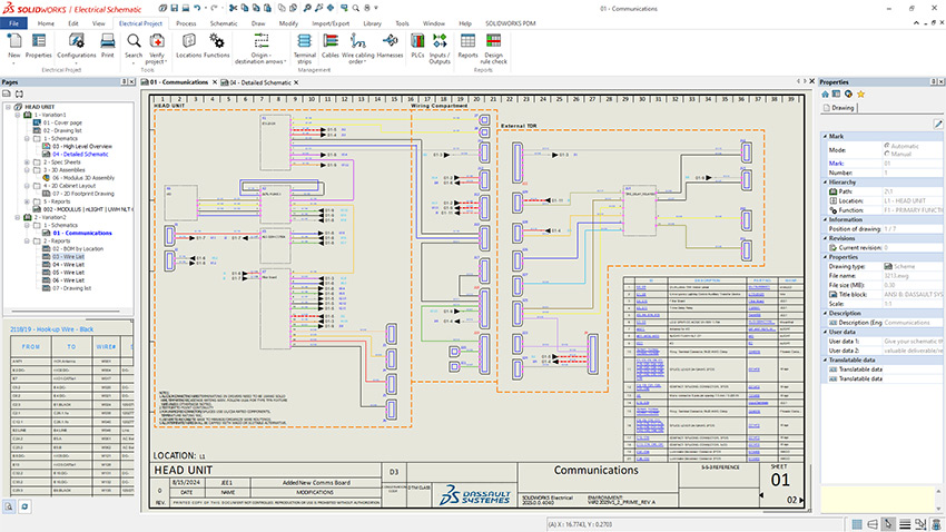
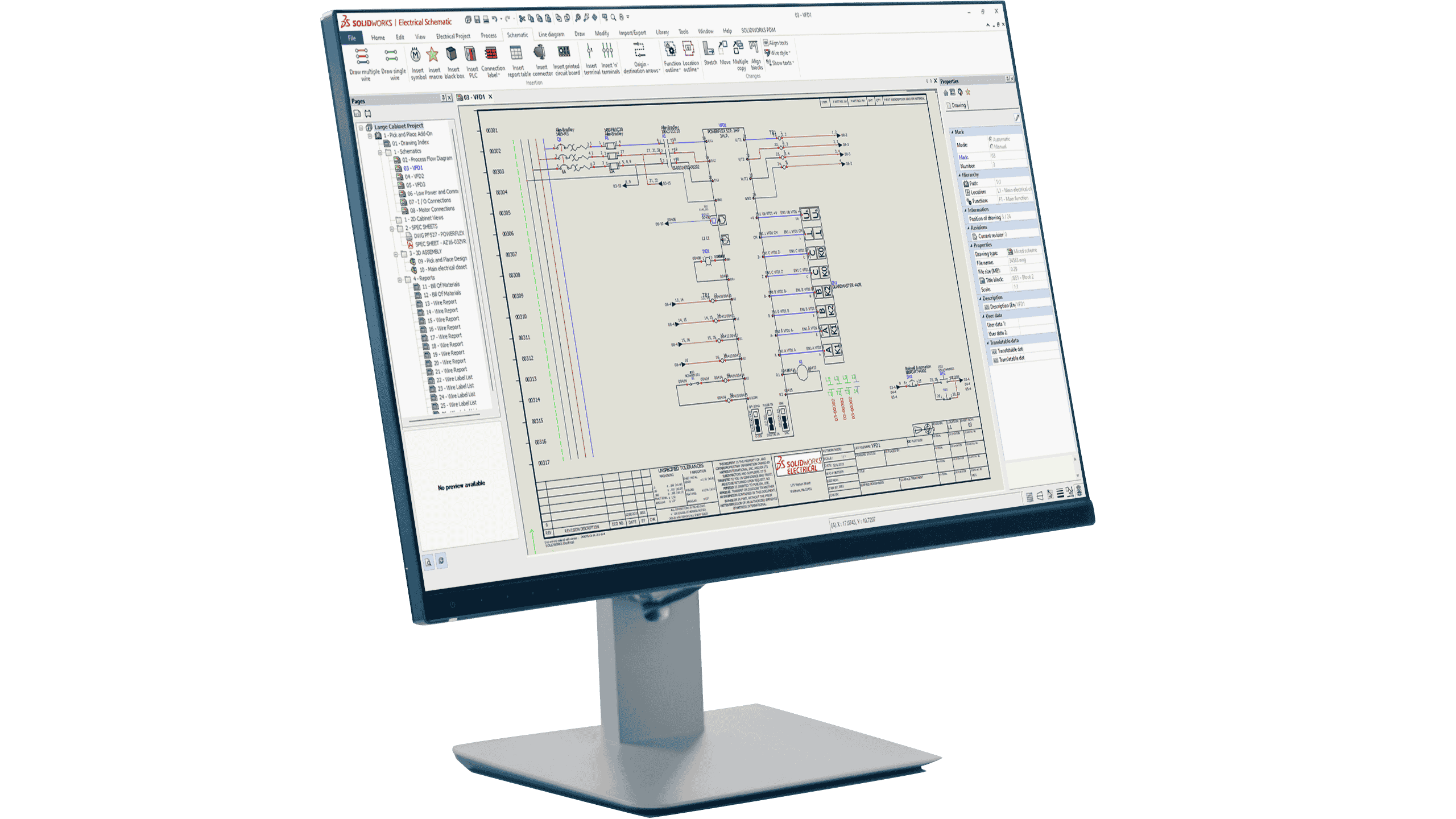
Schematic design is the process of generating schematics, which are logical diagrams communicating a process or procedure. These schemes tell you what components are in a system and clearly represent how those components are connected, whether it’s in wiring, piping, or flow diagrams. Schematics are used across disciplines including everything from electrical engineering and PFD/P&ID to pneumatics and hydraulics.

Schematics vs Layouts

Schematic design is a critical step in any design workflow or documentation process. Often, design and engineering projects will start with schematic drawings. Schematics provide a clear, easy to read overview of a system’s components and their connections, and are then used to inform the creation of layout drawings.

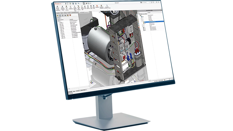
Layouts are mechanical drawings that accurately depict the physical arrangement of components in the context of a complete product. These are most commonly done in 2D, but you can also have 3D layouts which have a range of benefits for all teams including higher quality documentation and production-optimized designs.

Why is Intelligent Schematic Design Important?

SOLIDWORKS user interface showing electrical schematic design

Intelligent schematic design supercharges your design workflow. These tools empower your engineers and designers to focus on innovation by eliminating the need for manual completion of rote tasks, saving both time and effort.

Intelligent schematic design tools, like those offered in the SOLIDWORKS® Electrical product suite, have a database foundation and provide helpful assistance in your design workflow. Ultimately, this intelligence leaves you in control of every action and eliminates human error and time wasted on tedious tasks like updating wire numbers, automating component tagging, swapping parts, or reusing circuits.

Ultimately, intelligent schematic design tools help your teams save time, eliminate errors, and innovate faster by cutting out mundane, error-prone, and tedious tasks, thus freeing up time for your engineers and designers to focus on creating powerful designs.
 

Interested? Check out the SOLIDWORKS Electrical intelligent schematic design tools View products

Who is Involved in Schematic Design?

Considering schematic design’s broad scope, let’s break down some of the key players to narrow in on who is involved with schematic design.

SOLIDWORKS icon for Electrical Engineer

Electrical Engineer


Electrical engineers and electrical systems designers are heavily involved in the creation of schematics. Electrical engineers and designers will draft electrical schematics as a first step in the electrical documentation and design process, requiring an understanding of both the system’s overall logic and physical component layout. Electrical schematics allow engineers to outline, from a system level, how components are connected, ensuring that all teams are on the same page before diving deeper into a product’s specifics.

SOLIDWORKS icon for Pneumatic System Designer

Pneumatic System Designer


Pneumatic system designers rely on clear, organized schematics for a smooth and efficient design process covering both system logic and component layout. Used across industrial control, automotive, and manufacturing, pneumatic systems depend on the spatial arrangement of their components and the precise circuits needed to maximize their efficacy and safety. By starting with schematic design as a first step, pneumatic system designers ensure they approach each new design project with a unified view of their systems’ logic, layout, and function.

SOLIDWORKS icon for Hydraulic System Engineer

Hydraulic System Engineer


Similar to a pneumatic system designer, hydraulic system engineers are focused on fluid power systems. Hydraulic system engineers and designers are not only responsible for selecting components for hydraulic circuits, but also for optimizing and securing the systems they design. The benefit of having well-built schematic designs at the start of the engineering process cannot be understated. Clearer schematics mean better aligned teams and thus reduced friction and quicker time to market.

SOLIDWORKS icon for System Architect/Process Engineer

Systems Architect / Process Engineer


Some other common players within the schematic design space include system architects, process engineers, and others involved in the design, drafting, and engineering world. As covered above, the application of schematic design extends beyond electrical, pneumatic, and hydraulic systems and can be extremely useful in providing a systems-level overview of all the necessary components for any project, be it in electrical, fluid power, PFD/P&ID, or beyond.

Where is Schematic Design Used?

Schematic design is used in almost every industry that deals with products, power systems, building and manufacturing, technologies, or design. Below are just some of the industries that rely on schematic design.

Are you a student? Check out these other learning materials View now

Our Schematic Design Solutions

SOLIDWORKS offers a range of schematic design tools in its SOLIDWORKS Electrical portfolio. Let’s take a look.

Let’s Dive Deeper

Schematic design has wide-reaching applications spanning industries, use cases, and job titles. Below, we’ve collected some of our favorite resources that dive deeper into schematic design and its related applications to help you learn more.