Introduction to ECAD

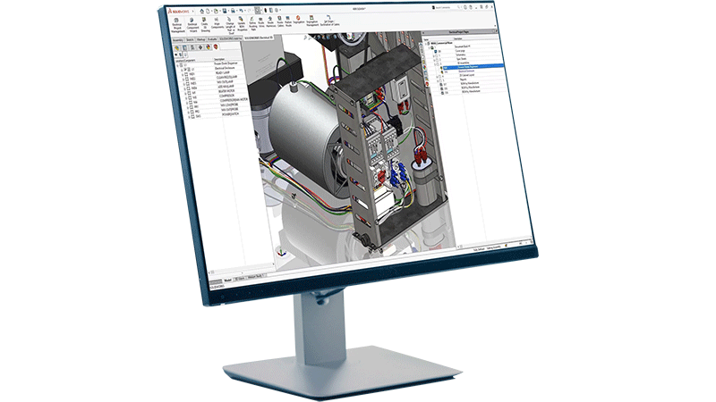
ECAD—short for Electronic Computer Aided Design or Electrical Computer Aided Design—is the software engineers use to design, document, and validate electrical and electronic systems before anything gets built. Whether you're laying out an industrial control panel, routing a wire harness through a machine frame or designing a printed circuit board for an embedded system, ECAD software gives you the precision, structure, and automation to do it right.

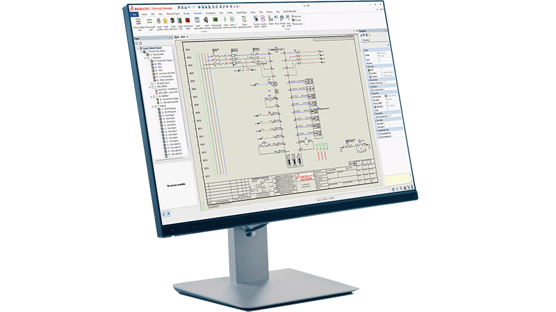
The term covers a wide range of design activities. On the traditional electrical engineering side, that means electrical schematics, terminal strip layouts, wire and cable documentation, and panel design. On the electronics side, it extends into printed circuit board (PCB) layout, circuit design and simulation, and design rule checking. Both disciplines depend on ECAD—and increasingly, they depend on each other.

As electrical and mechanical systems become increasingly integrated, ECAD continues to be a foundational part of modern product development. It's not just a drafting tool. It's a design environment that connects engineering teams, reduces costly errors, and accelerates the path from concept to production.

ECAD in Traditional Electrical Engineering

For electrical engineers working on industrial systems, control panels, and complex machinery, ECAD is the backbone of the design process. These engineers are designing full systems rather than focusing solely on individual components in isolation. That means specifying power distribution, laying out control logic, documenting every wire and terminal, and ensuring the final product can be built, inspected, and maintained safely.

icon depicting schematic design creation

Electrical Schematics

Electrical schematics are the starting point. ECAD tools allow engineers to create detailed, standards-compliant schematic diagrams that define how electrical components connect and interact. Unlike generic drawing tools, purpose-built, intelligent ECAD software automatically links the schematic to downstream documentation, so a change in one place propagates across the entire project. This kind of electrical design automation is key to accelerating product development and reducing errors introduced by continual manual edits.

icon depicting wire harnessing in SOLIDWORKS on a desktop screen

Wire Harnessing

Wire harnessing adds another layer of complexity. In machines, vehicles, and industrial equipment, wire harnesses route power and signals through a physical structure. ECAD tools let engineers define the harness topology, specify wire gauges and colors, generate cut lists, and produce formboard drawings that manufacturing teams can use directly on the shop floor. Design for manufacturability, especially for wire harnessing applications, is crucial to align teams and reduce unnecessary roadblocks in the product development process.

interconnected squares showing a connected workflow, in this case representing terminal strip layout

Terminal Strip Layout

Terminal strip layout is another area where ECAD delivers real value. Manually arranging and documenting terminal blocks is time-consuming and error-prone. ECAD tools automate the generation of terminal strip diagrams directly from the schematic, ensuring that the physical layout matches the design intent without manual re-entry.

icon depicting virtual design validation

Industrial Control Panel Design

Industrial control panel design brings together schematics, component selection, enclosure layout and wire documentation into a single coordinated workflow. Engineers can place components in panel layout drawings, check clearances, generate wire lists, and produce manufacturing documentation, all from one connected design environment.

These workflows demand accuracy. A mislabeled wire, a missed terminal or an incorrect component reference can cause production delays, safety issues, or costly rework in the field. ECAD tools reduce that risk by keeping design data connected, consistent, and traceable from the first schematic to the final assembly drawing.

ECAD in Electronics Design

Electrical design and electronics design are both two fully distinct disciplines. In electronics design, the focus shifts to the design of printed circuit boards, integrated circuits, and embedded systems. While the underlying goal to design electrical systems accurately and efficiently remains the same, the tools and workflows differ significantly.

	solidworks-HiTech-industry-Smaller Space-Higher Power

Schematic Capture

Schematic capture in electronics design defines the logical connections between components, such as resistors, capacitors, ICs, connectors and more. From the schematic, engineers transition to PCB layout, where those components are physically placed on a board and connected through routed copper traces.

icon depicting approval path, in this case depicting design rule checking (DRC)

Design Rule Checking

Design rule checking (DRC) is a critical step in PCB design. ECAD tools automatically verify that the layout meets manufacturing constraints—trace widths, clearances, drill sizes and more—before the design goes to fabrication. This catches errors early, when they're cheap to fix, rather than after boards have been manufactured.

icon depicting simulation over a bar graph with varying levels

Simulation Tools

Simulation tools within ECAD environments allow engineers to validate signal integrity, analyze power distribution, and test circuit behavior virtually. This reduces the number of physical prototypes needed and speeds up the validation cycle.

Key Features of ECAD Tools

image depicting woman using electrical design software on a laptop

Whether you're designing a control panel or a circuit board, effective ECAD tools share a core set of capabilities:

  • Schematic design: Create standards-compliant electrical diagrams with intelligent component libraries and automatic cross-referencing.
  • Design rule checking: Automatically validate designs against manufacturing and safety standards to catch errors before they reach production.
  • 3D integration: Visualize electrical designs in three dimensions and coordinate with mechanical CAD models to resolve conflicts early.
  • Automated documentation: Generate wire lists, terminal diagrams, bill of materials and manufacturing drawings directly from the design data—no manual re-entry required.
  • Component management: Maintain centralized libraries of electrical components with accurate specifications, reducing selection errors and supporting procurement workflows.
  • Collaboration tools: Enable multiple engineers to work on the same project simultaneously, with version control and change tracking to maintain design integrity.

ECAD vs MCAD: How They Work Together

image showing zoomed in view of inside an industrial control panel containing various connectors, wiring, and terminal strip elements

ECAD and MCAD (Mechanical Computer-Aided Design) address different aspects of product development, but modern products almost always require both. Understanding where each tool excels—and how they connect—is essential for any engineering team working on electromechanical systems.

MCAD tools focus on the physical, three-dimensional geometry of a product: enclosures, brackets, structural components, mechanisms, and assemblies. ECAD tools focus on the electrical systems within or around those physical structures: wiring, schematics, control logic, and PCB layouts.

The challenge is that electrical and mechanical designs don't exist in isolation. A wire harness has to route through a physical enclosure. A control panel has to fit within a machine frame. A PCB has to mount inside a housing with specific thermal and clearance requirements. When ECAD and MCAD data live in separate, disconnected tools, conflicts between the electrical and mechanical design are discovered late, and late discoveries are expensive.

ECAD/MCAD integration solves this by enabling electrical and mechanical teams to work in parallel while sharing a common data model. Changes to the mechanical design are visible to the electrical team, and vice versa. This reduces rework, shortens design cycles, and produces a more accurate bill of materials.

All industries depend heavily on ECAD/MCAD collaboration, including industrial machinery, automotive, aerospace, building automation, and consumer electronics—anywhere that electrical systems live inside complex mechanical products.

Key Players in the ECAD Space

icon depicting an electrical design engineer

Electrical Design Engineer

Electrical design engineers are the primary users of ECAD tools in traditional engineering environments. They create and maintain electrical schematics, specify components, design control panel layouts and produce the documentation that manufacturing teams use to build the system. For an electrical engineer, ECAD tools are a daily necessity—not just for drafting, but for managing the full complexity of an electrical system across revisions, variants and team members.

SOLIDWORKS icon depicting PCB designer

PCB Designer

PCB designers work within the electronics side of ECAD, translating circuit schematics into manufacturable board layouts. They manage component placement, trace routing, layer stack-up and design rule verification. Their work sits at the intersection of electrical engineering and manufacturing, and they rely on ECAD tools to ensure that what they design can actually be built reliably and at scale. Relatedly, for embedded system developers, ECAD tools also connect to hardware description languages and FPGA design workflows, bridging the gap between hardware and firmware development.

SOLIDWORKS icon depicting a systems engineer or engineering manager

Systems Engineer / Engineering Manager

Systems engineers and engineering managers oversee the integration of electrical and mechanical subsystems into a complete product. They use ECAD outputs—schematics, BOMs, wire lists—to coordinate between disciplines and ensure that the design meets system-level requirements. For these roles, ECAD's ability to produce consistent, connected documentation across the entire design is as important as any individual feature.

SOLIDWORKS icon depicting a manufacturing engineer

Manufacturing Engineer

Manufacturing engineers receive ECAD outputs and use them to plan and execute production. Wire lists, terminal diagrams and formboard drawings drive the assembly process. Accurate ECAD documentation reduces assembly errors, supports quality control and makes it easier to train technicians on complex wiring tasks. When ECAD tools are well integrated into the design-to-manufacturing workflow, manufacturing engineers spend less time interpreting ambiguous drawings and more time building.

How SOLIDWORKS Supports ECAD Workflows

SOLIDWORKS offers dedicated ECAD tools designed specifically for the workflows that electrical engineers depend on. SOLIDWORKS Electrical provides a complete environment for electrical systems design, covering schematic creation, panel layout, terminal strip documentation, wire harnessing and 3D integration with SOLIDWORKS Design.

Trusted by more than eight million users and 500,000 companies worldwide, SOLIDWORKS delivers tools built for engineers by engineers—with continuous, user-driven enhancements that keep pace with the demands of modern electrical design. Explore all of the SOLIDWORKS Electrical solutions here.

Learn More About ECAD

Frequently Asked Questions


How Can We Help?

SOLIDWORKS Flexible Solution icon of two dialogue quote boxes

Find the Flexible Solution for You

Speak with a SOLIDWORKS expert to discuss your business needs.

SOLIDWORKS Support icon of people standing together

Find SOLIDWORKS Support

Get technical support for SOLIDWORKS products and explore ways to grow your skills.

solidworks-intuitive-user-interface-icon.png

Buy SOLIDWORKS Solutions

Flexible purchasing options give you the power to choose a license that best suits your needs.